At this time have met many automated protection tools against touch voltages. This equipment is not limited to the human security of the electric shock, but developing wider security building attached to the network installation of fire hazard due to electrical short circuit (short circuit).
.
1 Types of Automatic Protection Tool
The types of protective devices are widely used, among others, are: Residual Current Device (RCD), Earth Leakage Circuit Breaker (ELCB) and Ground Fault Circuit interruptor (GFCI). Despite the different names, but the principle is the same, ie it will work or active when it detects a leakage current to ground. Because of that ability, the leakage current is analogous to the electric shock current flowing in the human body.
2 Principles of Automatic Protection Tool
Figure 1 below shows the physical shape of an RCD for a single-phase system and scheme diagram is shown in Figure 2.


4 Procedures Public Safety
a. Only those authorized and competent are allowed to work on or around electrical equipment
b. Using electrical equipment in accordance with the procedure (do not damage or malfunction makes safety devices or protective equipment).
c. Do not use metal ladders for electrical installation work in the area
d. Maintain equipment and electrical installation system with both
e. Preparing an emergency action steps when an accident
- Shut-down procedure: electric breaker button (emergency off) should be easily achieved.
- First aid to victims
f. First aid to the man who was electrocuted
- Victims should be separated from the flow of electricity in a safe manner prior to the first aid

- Contact section authorized to perform first aid. First aid should be done by a competent person.
5. Special Safety Procedures
a. Procedure Lockout / tagout
This procedure is a specific safety procedures necessary when working to perform maintenance / repairs on the system and the installation of electrical equipment safely.
b. purpose:
- Prevent release either electrically or mechanically unintended harm to people who are doing the work and the maintenance or repair,
- Separating / disconnect from the mains.
c. The steps of this procedure can be explained as follows
- Create a plan of lockout / tagout
- Tell the operator and other users planned power outages
- Decide flow at the appropriate point
- Check whether the team / workers have been hanging labels (padlocks) signs of improvement at the point of lockout
- Put the word "attention" to the point of lockout
- Remove the residual energy / stored (such as in batteries, capacitors, per and so on)
- Ensure that the equipment / system is not electrified
- All members of the team / workers take labels (padlock) was back after the work is completed.
.
1 Types of Automatic Protection Tool
The types of protective devices are widely used, among others, are: Residual Current Device (RCD), Earth Leakage Circuit Breaker (ELCB) and Ground Fault Circuit interruptor (GFCI). Despite the different names, but the principle is the same, ie it will work or active when it detects a leakage current to ground. Because of that ability, the leakage current is analogous to the electric shock current flowing in the human body.
2 Principles of Automatic Protection Tool
Figure 1 below shows the physical shape of an RCD for a single-phase system and scheme diagram is shown in Figure 2.

Figure 1 Physical form RCD 1 phase

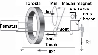
Figure 2 Schematic diagram 1 phase RCD
The working principle of RCD can be explained as follows (note the schematic diagram in Figure 2):
Iin: inflows
Iout: outflow
IR1: residual current that flows into the body
IR2: residual current flowing to ground
Min: the magnetic field generated by the inflow
Mout: the magnetic field generated by the outflow.
In the case of leakage current circumstances, then the outflow is less than inflow, Iout <Iin and residual currents flowing out after going through the human body or the ground. Because Iin> Iout then Min> Mout, the consequences would arise induced emf in coil wrapped around the toroid so that the induced emf activate the circuit breaker equipment.
While the physical form ELCB for three-phase system is shown in Figure 3 and the schematic diagram is shown in Figure 4 below.

Figure 3 Physical 3 phase ELCB

Figure 4 Schematic diagram 3 phase ELCB
The working principle of safety / protection for the automated three-phase system can be described as follows (note the schematic diagram of Figure 4):
If there is no leakage current (to ground or the human body), the resultant amount of current flowing in the fourth conductor is zero. So that the current transformer (CT) did not experience electromagnetic induction and the trigger is not active. In case this does not happen in the system. On the contrary, if there is leakage current, then the amount of the resultant current is not equal to zero, then the current transformer (CT) induce stress and activates the trigger so that the tool is working power breaker disconnects the load from the source (network).
Figure 5 and Figure 6 shows the use of the CRD or ELCB. If security for the type of load only the RCD fitted to the instrument input channels only. Meanwhile, when the security for all tool / load and channel, then the safety device mounted on the side of the input / source all loads. Which is best, depending on what is desired. If you desire security for all the circuits, the selected picture 6. But the economic aspects need to be considered, because the larger the flow capacity that must be served, then the price will be more expensive the tool, although the current limit security (leak) the same.

Figure 5 Installation of ELCB on load (local protection)

Figure 6 Installation ELCB on the source network (centralized protection)
For devices mounted on the table, enough with the current security Din = 30 mA, whereas to-use tools attached to the body (bath tube, sauna, beard cutting tools, etc.) to use safety devices with lower currents , ie DIN = 10 mA. For protection against fire (centralized protection) fitted with DIN = 500 mA.
3 Protection in Portable Equipment
Methods of security or protection of portable electrical equipment can be divided into two classes, namely Class I and Class Tool II. As for the tools children's toys are categorized as Class III devices.
a. Tool Class I is a power tool that safeguards against electric shock using channel ground (grounding). This device has an enclosure (chassis) that is made of metal.
b. Tool is a Class II power tool that has a double insulation, where the enclosure or the parts are touched in the use made of insulating material. In this class of devices is not necessary grounding line. The following are examples of tools that include Class I and Class II.
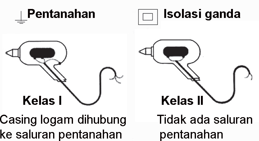
Figure 7 Example of the classification of protection on portable electrical appliances
a. Only those authorized and competent are allowed to work on or around electrical equipment
b. Using electrical equipment in accordance with the procedure (do not damage or malfunction makes safety devices or protective equipment).
c. Do not use metal ladders for electrical installation work in the area
d. Maintain equipment and electrical installation system with both
e. Preparing an emergency action steps when an accident
- Shut-down procedure: electric breaker button (emergency off) should be easily achieved.
- First aid to victims
f. First aid to the man who was electrocuted
- Victims should be separated from the flow of electricity in a safe manner prior to the first aid

Figure 8 Separation of the victim from the mains
5. Special Safety Procedures
a. Procedure Lockout / tagout
This procedure is a specific safety procedures necessary when working to perform maintenance / repairs on the system and the installation of electrical equipment safely.
b. purpose:
- Prevent release either electrically or mechanically unintended harm to people who are doing the work and the maintenance or repair,
- Separating / disconnect from the mains.
c. The steps of this procedure can be explained as follows
- Create a plan of lockout / tagout
- Tell the operator and other users planned power outages
- Decide flow at the appropriate point
- Check whether the team / workers have been hanging labels (padlocks) signs of improvement at the point of lockout
- Put the word "attention" to the point of lockout
- Remove the residual energy / stored (such as in batteries, capacitors, per and so on)
- Ensure that the equipment / system is not electrified
- All members of the team / workers take labels (padlock) was back after the work is completed.
No comments:
Post a Comment